Paramecium/Arduino interface build instructions
Project description and video of mind controlled microbes are here.
Download
This zipfile contains the laser cutting pattern for the stand in Adobe Illustrator and SVG format, and the source code for some basic Arduino sketches to control paramecia with a joystick or a brain sensor.
Components
You’ll need the following parts to build the system:
-
Arduino (any model)
-
Hootoo Webcam: This ‘10 Megapixel with night vision feature’ is more like a one megapixel camera, and the ‘night vision’ amounts to a few white LEDs mounted around the lens, but what makes it ideal for this project is that the lens is able to focus close enough to the camera to get a crisp, magnified image of the 14mm x 14mm well with the paramecia in it. Mac users: don’t let the ‘doesn’t work with OS X’ warning in the description put you off; I use a Mac with this camera and it works fine for our purposes.
-
Paramecium: I recommend paramecium multimicronucleatum (link goes to Connecticut Valley Biological) or paramecium caudatum (link goes to Carolina). Both species are on the larger end of the paramecium size scale, and are a good size for webcam viewing or image processing.
-
Mechanical pencil leads for use as electrodes, 0.7mm diameter. The softer the lead, the higher the graphite content, which makes for a better conductor. I use 2B leads from Pentel, which are readily available.
-
Hookup wire: 22 AWG solid wire works well (e.g. Newark part number WH220025)
-
For a simple and cheap control system you can use a small joystick: the Parallax thumb joystick, also available from DigiKey or Adafruit works well and is easy to interface to the Arduino.
-
To control the paramecia with your mind, you’ll need a brain sensor. The cheapest one I’ve been able to find is from the MindFlex Duel, which gives you two sensors for about $40. There are great illustrated instructions on how to hack one to connect to an Ardino here.
-
Copper tape, 1/4” wide. There are two main kinds of copper tape, one with conductive adheisve and one without. Make sure you get the kind with the conductive adhesive (e.g. McMaster part number 76555A711).
-
M6 threaded rod, 40mm long (McMaster part number 90435A114)
-
3x M6 nuts (McMaster part number 90591A151)
-
4x M3 screws, 10mm long (McMaster part number 92005A120)
-
4x M3 nuts (McMaster part number 90592A009)
-
White LED: I use a Cree LED, DigiKey part number C513A-WSN-CV0Y0151-ND. It’s bright (>5000 mcd over a 55 degree beam span) and tolerant of the current output of an Arduino digital pin without requiring a resistor. Any white LED with similar specs should work fine. If your LED is to bright, attach it to a PWM pin and use a lower duty cycle to drive it.
Brain sensor notes
Warning:Brains and mains don’t go together well. Be very careful not to create a loop between the electrode on the brain sensor and anything with potentially brain-frying electrical current. I always use this setup with my laptop and disconnect it from the wall before plugging in the sensor. If you have to use this with a mains-powered computer, be careful not to touch anything plugged into the mains (including your computer) while wearing the sensor. Before you start, read the OpenEEG warning page; the same warnings apply to this project if you choose to go the brain control route.
The ‘concentration’ variable measured by the Neurosky chipset inside the brain sensor is a bit of a black box, and finding the right mental state to generate a high enough concentration value can take some trial and error. I recommend downloading something to visualize the output (e.g. this Processing brain grapher) and practicing with that first.
The sensor is quite sensitive to electrode placement, electrical noise, head movement and other environmental factors. Again, trial and error is your friend.
Building
-
There are three laser cut parts, a base and two legs. The base has an engraved square well in it for holding the paramecia. The taller leg holds the webcam, and should be attached on the side farther away from the square well. The shorter leg holds an LED for and should be mounted closer to the well.

-
Colour in the square well with a Sharpie. This will improve contrast when viewing paramecia. Sharpies are alcohol-based and will dry before you have finished constructing the project. Beware using other kinds of marker; if they do not dry then black marker will contaminate any liquid sample placed in the well of the base.

If you laser engraved your acrylic through the protective liner (as shown here), then you may want to wait until after you have coloured in the square to remove the liner from the base.
-
Attach the legs to the base. Each leg uses one M3 screw and nut, as shown:

You can hand tighten the screw or use a screwdriver. Be careful not to overtighten the screw as this can stress the acrylic.
-
Cut off a piece of hookup wire and strip about 3cm off one end. This will be used to connect to the Arduino, so give yourself enough length to do so comfortably. Choose one of the four pairs of small holes on the base and pass the wire through one of the two holes from the bottom as shown:
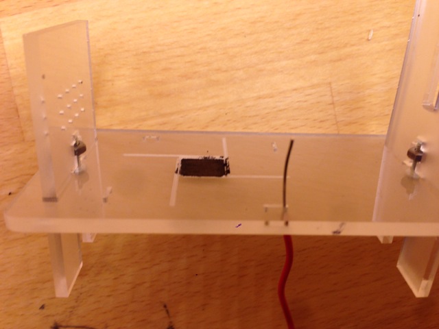
Pass the end of the wire back through the adjacent hole, forming an upside-down ‘U’, and tie off the wire under the base:

Repeat for the other three pairs of holes:
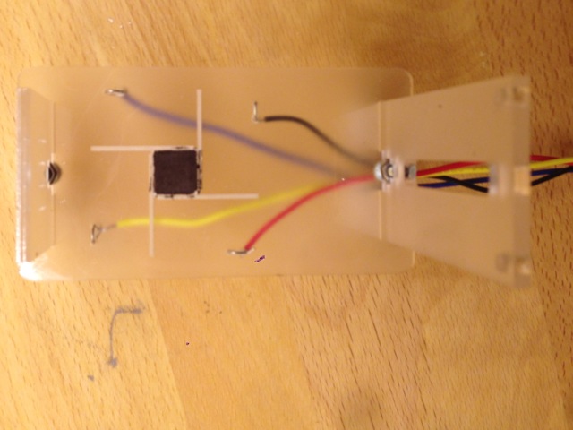
Strip off about a centimeter of wire on the other end to attach to the Arduino later.
-
Trim pencil leads to size and mount in the four channels surrounding the well to form the four electrodes:

The channels are just guides; the electrodes do not have to lie perfectly in them. Make sure that none of the electrodes is touching any of the others.
-
Use a piece of conductive tape to join one of the electrodes to the nearest ‘U’ of wire sticking through the board. If your tape is perpendicular to the nearest edge, you can optionally wrap the tape around the edge and stick it to the bare wire on the bottom as well for even better electrical contact.

Add two shorter perpendicular pieces of tape, one covering the wire ‘U’ and one covering the electrode. Make sure that electrode is well stuck down, and that the copper tape does not reach all the way to the square well.
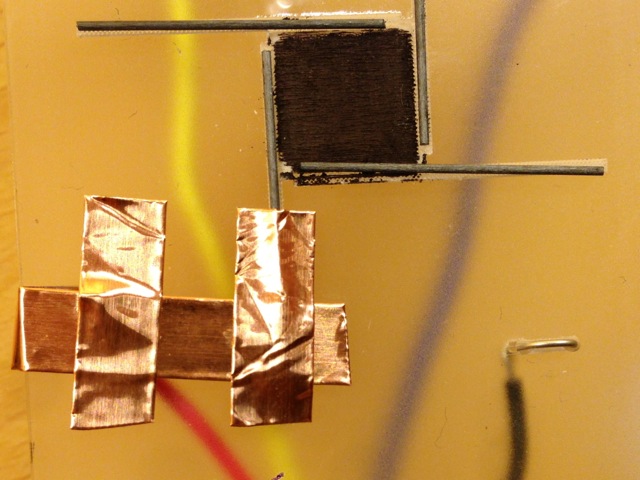
Repeat for the other three electrodes. For the two electrodes where the first piece of conductive tape runs parallel to the edge, you can extend the perpendicular piece of tape covering the wire ‘U’ to the other side of the base and stick it to the bare wire on the bottom (as shown for the yellow and black wires below)
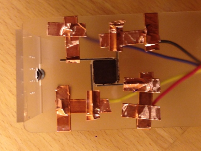
If you own a multimeter, now would be a very good time to check continuity for each of the four electrodes. Place one probe on the electrode and the other at the far end of the hookup wire. If there are any poor connections make sure that the copper tape is stuck down well, and add extra tape if necessary.
-
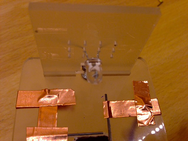
Push the pins of the white LED through two of the holes in the shorter leg on the base. The middle two holes usually work well.
-
Remove the bottom of the stand from the webcam. On the side of the stand you will see two rubber plugs. Remove both of these to expose a small Phillips screw underneath. Unscrew the screw and remove the bottom part of the stand.
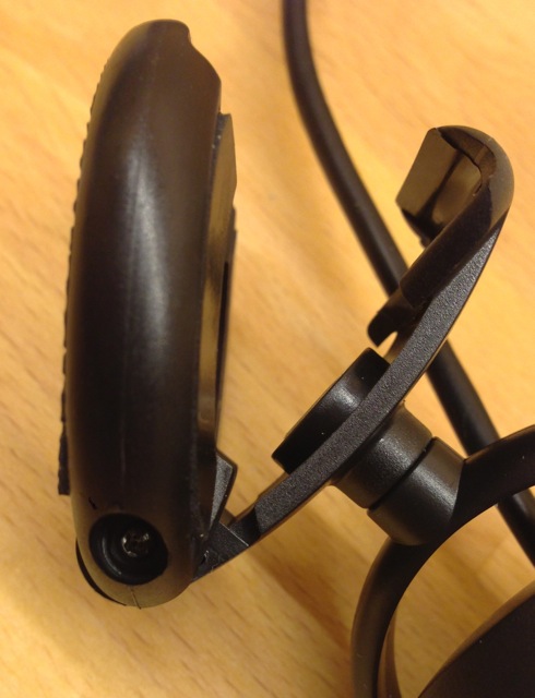
Now is a good time to roughly adjust the focus of the webcam, since it’s harder to manipulate the focus ring when the camera is mounted. You don’t have to do a wonderful job at this point, just make sure that the focus is fairly near the camera. Don’t force the focus ring: applying too much pressure can damage the image sensor in the camera.
-
On the base of the webcam is an M6 nut. Screw one end of the M6 threaded rod onto this. Take care not to screw with too much force or the nut may pull out of its housing. If this happens, simply replace the nut and optionally add a dab of hot glue to keep it in place.
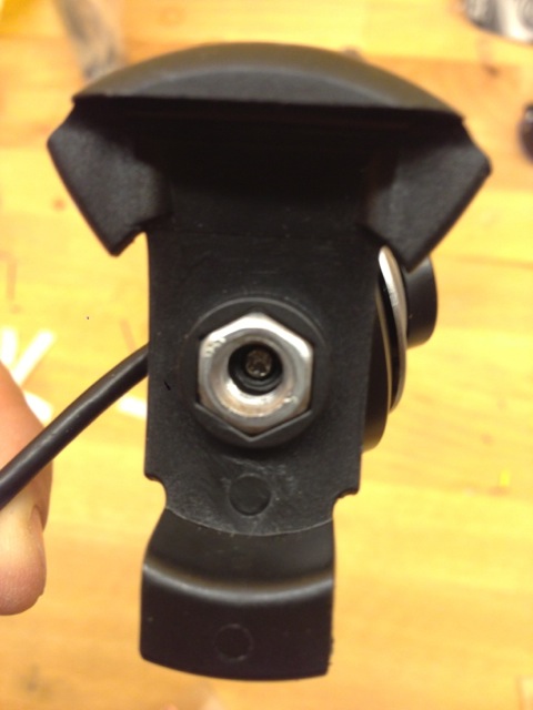
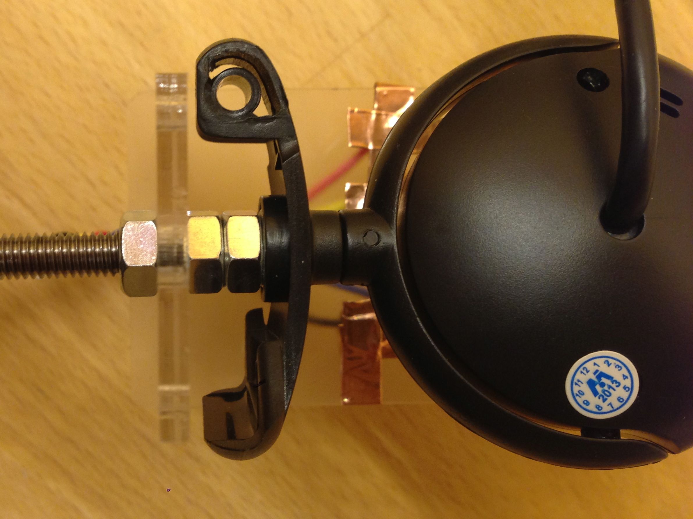
Screw two nuts onto the threaded rod to act as spacers, then slide the rod through the slot in the taller leg and add a third nut on the outside to loosely hold the rod in place.
-
Connect the longer (positive) lead of the LED to pin 13 on the Arduino, and the shorter (negative) lead to the nearby GND pin on the Arduino, using alligator clips or another connection method. Connect the four electrodes to pins 4, 5, 6 and 7 on the Arduino.
Finally, attach the X axis of the joystick to analog port A0 and the Y axis to A1, then run the example sketch. If you’re using a brain sensor, follow these instructions to hook it up to your Arduino.
The final assembly should look like this:

You can optionally attach the Arduino to the base by screwing it to the two holes at the top of the longer leg with two more M3 screws and nuts.